Larry Ellison's Driveway (a.k.a. CS270 Project)
Odds and Ends
Small Edges
If one examines the drawings in detail, it becomes apparent that many
of the generated stones have very short edges. This can cause problems
because of the lack of accuracy in the cutting process. Fortunately,
the grout space between stones gives some leeway in the shapes.
A processing step is added after generation in which small edges are
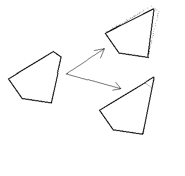
removed. There are two possible algorithms to remove edges, as
demonstrated below. In the first, the adjacent edges are simply
extended to their meeting point. This approach can cause the edges to
impinge on the adjoining stone, but the combination of grout space and
the ability to cut onsite makes this feasible. The other solution is
to move the adjacent edges until they meet at the midpoint of the
removed edge. The drawback to this approach is that the grout lines
will no longer be even. It is, of course, possible to split the
difference between the two methods.

How to Remove Small Edges
Uneven grout lines were undesirable, so the first option was
chosen. Edges shorter than 0.6 inches were removed.
Modifying By Hand
At one point, my architect friend pointed to one particular place in
the image where four stones met in a corner (this is possible even
after the local patterns are
removed). "Can you remove that?", he asked. In response, I developed a
user interface in matlab (see Tools) that
allows an individual point to be flipped. This allows local problem
areas to be addressed, although simply saving the random seed is no
longer sufficient to regenerate the image.
Maps and Drawings
In order for the stone masons to cut the individual stones, drawings
of each stones must be provided. In order to place the stones
correctly once they're delivered, a map must be generated. Both of
these documents are generated automatically. The stone designs come
from the unique list of polygons, while the map is generated by adding
a label to each stone based on to which unique stone it maps. For
example, the following image is a map of the last figure on the previous page. Negative
indices indicate a reflection from the positive equivalent (e.g. -2 is
stone 2 upside down). Only the interior is considered to avoid edge
effects, since the edge cells of a Voronoi diagram are unbounded.

A Map
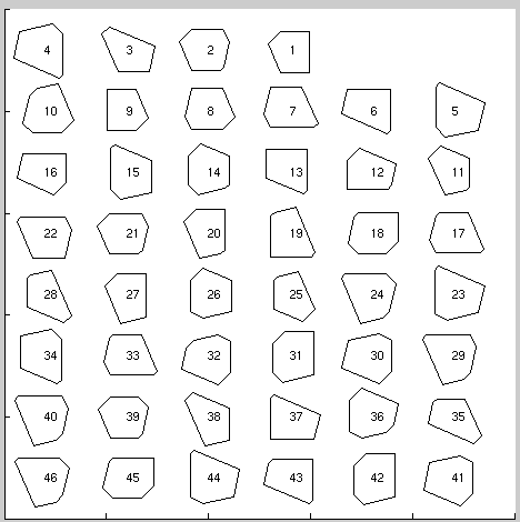
Next is the diagram of the unique stones that compose the above
figure. For final delivery, both of these diagrams were converted into
MiniCAD format (a fairly big task in itself), and dimensional drawings
were generated.

The Unique Polygons
Prev TOC Next
Adam Janin
janin@icsi.berkeley.edu


